 |
|||
|
|
|||
|
|
|||
| ||||||||||
|
|
 TM 11-6625-2884-30/NAVAIR 16-35TS3615-2
CONTROL AND POWER DISTRIBUTION (Continued)
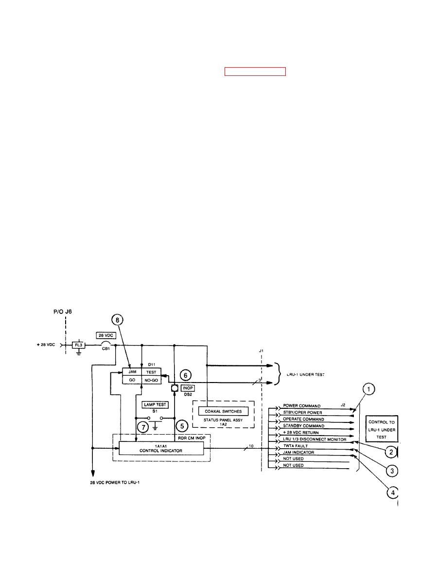
e. Status Signals from LRU-1 (refer to Figure FO-13).
(1)
STBY/OPR POWER (DQTDOPR): The STBY/OPR Power (+28 V dc) is received
from the low voltage power bus in LRU-1 when the control indicator
is switched to standby or operate. The +28 Vdc enables the 180
second time delay relay and supplies +23 V to the ON, STBY and OPR
indicators in Control Indicator 1A1A1.
LRU-1 DISCONNECT MONITOR (GOP28ST): The LRU-1 disconnect
(2)
monitor (ground) is received from LRU-1 and energizes the LRU-1
disconnect monitor relay in Control Indicator 1A1A1.
TWTA FAULT (OVPT FLT): When a fault occurs in the high voltage
(3)
power supply or traveling wave tube amplifier or if an overtempera-
ture condition occurs in LRU-1, a TWTA fault signal is generated.
This causes the fault relay in the control indicator to
de-energize, generating an INOP (5) ground level signal,
illuminating the INOP (6) lamp on the control panel.
JAM INDICATE (1YJAM): When LRU-1 is transmitting active ECM, the
(4)
JAM INDICATE signal (high level) is received from the high voltage
power supply in LRU-1. This causes the jam relay to energize in
the control indicator producing a JAM (7) signal (ground level)
which illuminates the JAM (8) lamp on the control panel.
2-22
|
|
Privacy Statement - Press Release - Copyright Information. - Contact Us |
