 |
|||
|
|
|||
|
Page Title:
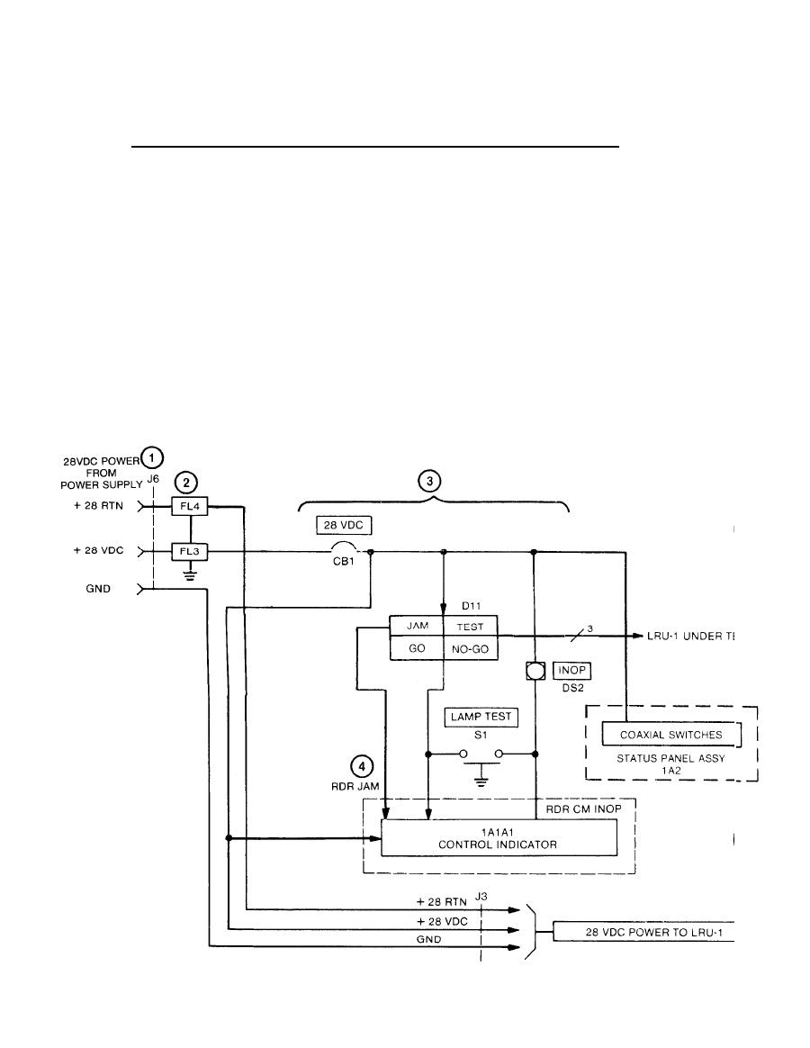
28 VDC Power Distribution to LRU-1 and the Control Indicator. |
|
||
| ||||||||||
|
|
 TM 11-6625-2884-30/NAVAIR 16-35TS3615-2
CONTROL AND POWER DISTRIBUTION (Continued)
28 VDC Power Distribution to LRU-1 and the Control Indicator.
c.
Power cable W7 connects 28 Vdc from the power supply to Input Power
(1)
28 VDC jack J6.
(2)
Line Filters FL3 and FL4 contribute to electromagnetic interference
(EMI) integrity. The filters eliminate conductive interference from
the BTS.
When circuit breaker CB1 is enabled, 28 Vdc is applied to control
(3)
indicator, UUT, one side of the JAM and INOP lamps and to YIG filter
coaxial switches on 1A2.
(4)
28 Vdc to the control indicator enables LRU-1 disconnect monitor
relay K3 which sets up conditions for entering the standby and
operate modes.
(5)
28 Vdc is routed through 28V POWER jack J3 to UUT via cable W3.
2-20
|
|
Privacy Statement - Press Release - Copyright Information. - Contact Us |
