 |
|||
|
|
|||
|
|
|||
| ||||||||||
|
|
 TM 11-6625-2884-30/NAVAIR 16-35TS3615-2
BLOCK DIAGRAM DESCRIPTION (Continued)
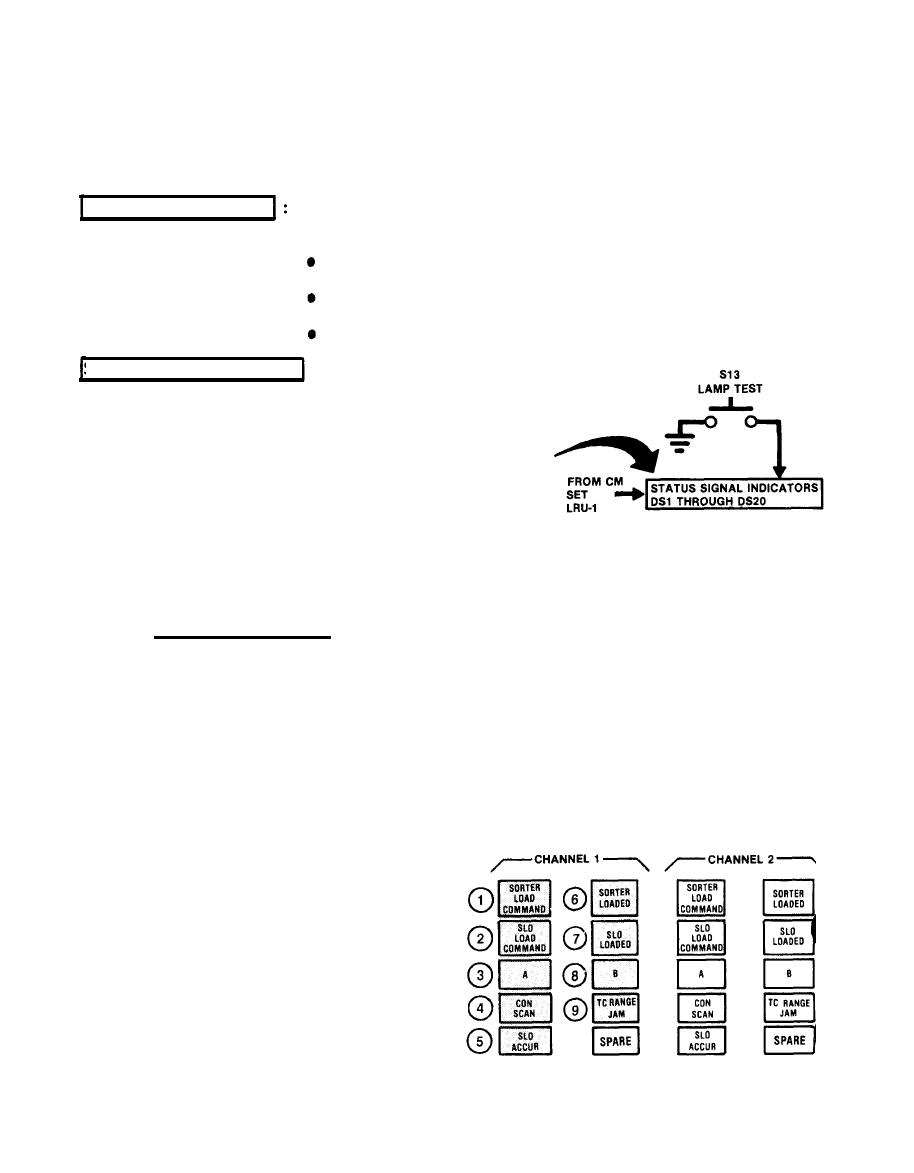
The LAMP TEST pushbutton (S13) lights all FORCING FUNCTION lamps on the Status
Panel for test purposes.
STATUS and MONITORING
The Status and Monitoring
Function consists of:
STATUS SIGNAL INDICATOR
VOLTAGE MONITOR SWITCH
OSCILLOSCOPE MONITOR
STATUS SIGNAL INDICATORS :
A total of 18 status
signals are received
from LRU-1 under test.
The signals are moni-
tored with indicator
lights DS1 through DS20
The Status Panel lamps
monitor Sorter 1 and
Sorter 2 in LRU-1 under
test. The Status Panel
lamps consist of the
following:
CHANNEL 1 (SORTER 1)
1
SORTER LOAD COMMAND (DS1)
2
SLO LOAD COMMAND (DS2)
3
THREAT A (DS3)
4
CON SCAN (DS4)
5
SLO ACCUR (DS5)
STATUS SIGNALS
6
SORTER LOADED (DS6)
7
SLO LOADED (DS7)
8
THREAT B (DS8)
9
TC RANGE JAM (DS9)
|
|
Privacy Statement - Press Release - Copyright Information. - Contact Us |
