 |
|||
|
|
|||
|
Page Title:
AC Power Distribution, Cooling and YIG FILTER CONTROL |
|
||
| ||||||||||
|
|
 TM 11-6625-2884-30/NAVAIR 16-35TS3615-2
BLOCK DIAGRAM DESCRIPTION (Continued)
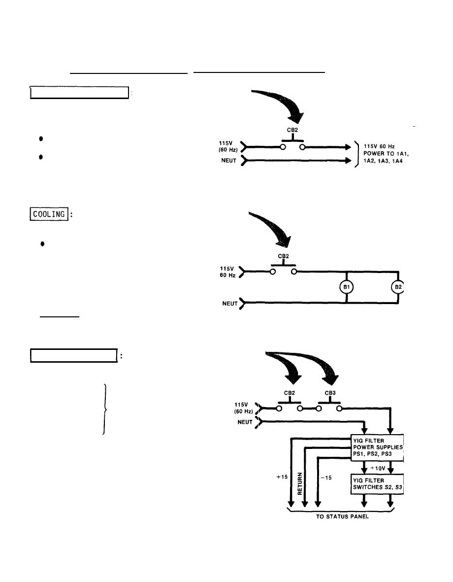
(2) AC Power Distribution, Cooling and YIG FILTER CONTROL
AC POWER DISTRIBUTION : When CB2 is enabled 115
V ac 60 Hz is applied to:
q CONTROL
PANEL 1A1
STATUS PANEL 1A2
RF MODULATION 1A3
q RF
MODULATION 1A4
When CB2 is enabled 115 VAC 60 Hz is
applied to:
CENTRIFUGAL BLOWER B1
q TUBEAXIAL
FAN B2
Blower B1 is used to cool LRU-1 under
test.
Blower B2 is used to cool the Bench
Test Set.
YIG FILTER CONTROL
Circuit Breakers CB2 and CB3
supply 115 V 60 Hz power to
power supplies PS1, PS2 and
PS3.
PS1 - 15 volts
TO YIG FILTER ON
STATUS PANEL
PS2 + 15 volts
TO YIG FILTER CONTROL
PS3 + 10 volts
SWITCHES
YIG FILTER IN/OUT switch S2 switches
YIG FILTER in and out of RF PATH.
The YIG FILTER CONTROL S3 thumbwheel
controls the YIG FILTER in status
panel 1A2 for the setting of RF
2-4
|
|
Privacy Statement - Press Release - Copyright Information. - Contact Us |
