 |
|||
|
|
|||
|
Page Title:
TABLE 2-4. RF MODULATION ASSEMBLY CONTROLS, INDICATORS AND CONNECTORS (cont) |
|
||
| ||||||||||
|
|
 TM 11-6625-2884-12/NAVAIR 16-35TS3615-1
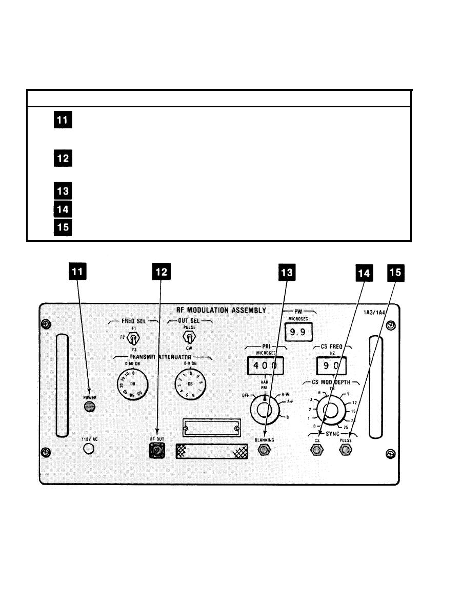
RF MODULATION ASSEMBLY 1A3/1A4 (Continued)
TABLE 2-4. RF MODULATION ASSEMBLY CONTROLS, INDICATORS,
AND CONNECTORS (Continued)
REFERENCE
DEVICE
FUNCTION
POWER indicator
When lit (green), shows the presence of
-15 V dc, confirming application of
115 V ac power to RF MODULATION ASSEMBLY.
RF OUT
Supplies high level modulated RF output,
controlled by transmit attenuators.
BLANKING
Supplies negative going blanking pulses.
SYNC CS
Supplies CS modulation sync.
SYNC PULSE
Supplies pulse sync.
2-14
|
|
Privacy Statement - Press Release - Copyright Information. - Contact Us |
