 |
|||
|
|
|||
|
Page Title:
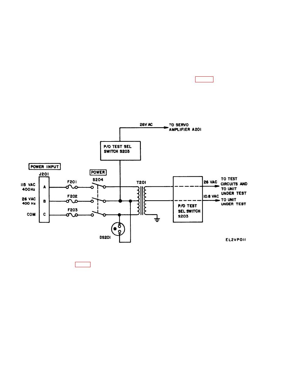
Power Supply Circuit |
|
||
| ||||||||||
|
|
 TM 11-6625-2843-14
(4) Transmitter test circuit for servoed indicators.
(1) The transmitter network includes a calibrated
(5) Low-inertia motor test circuit with served in-
synchro transmitter, a servoamplifier which is tied into
dicators.
the circuit for test of servoed indicators, circuits for
(6) Indicator test circuit for transmitters.
calibration and electrical zero checks of synchronous
(7) Indicator test circuit for differentials.
indicators, switches and potentiometers to facilitate
(8) Self-test circuit to verify proper operation of
low-inertia motor tests, and jacks for vtvm measure-
the test set.
ments
(9) Servoamplifier circuit.
(2) The indicator network includes a servoed syn-
chro indicator, a servoamplifier, and a selected synchro
locked at electrical zero to check diffenmtial synchros.
The power supply circuit (fig. 5-2) provides 26 and
10.8-volt outputa at 400 Hertz from 26-volt or 115-volt
b. The test circuits and applications discussed are:
inputs at 400 Hertz. The transformer primary has a
(1) Power supply circuit.
center tap that is used as an input during 26-volt
(2) Electrical zero test circuit for synchronous in.
operation, and as a 26-volt output during 115-volt
dicators.
operation. The 26 volts available at the transformer
(3) Transmitter test circuit for synchronous in-
dicators.
primary are used to energise servoamplifier A201.
Figure 5-2. Pawcr supply, schematic diagram.
and the stator is energized by 10.8 volts. The voltage
levels and phasing set up a magnetic field which causes
The electrical zero test circuit (fig. 5-3) is used to check
the rotor to assume a predetermined position with
the electrical zero of synchronous indicators. This test
is enabled by TEST SEL switch S203 at SYN IND and
respect to the stator. This position is considered the
electrical zero setting of the indicator and maybe used
SYN IND switch S202 at E-Z. With this test setup, the
as a reference to set the indicator dial.
rotor of the indicator under testis energized by 26 volts
|
|
Privacy Statement - Press Release - Copyright Information. - Contact Us |
