 |
|||
|
|
|||
|
Page Title:
Figure 3-11. Typical installation of RHAT for testing. |
|
||
| ||||||||||
|
|
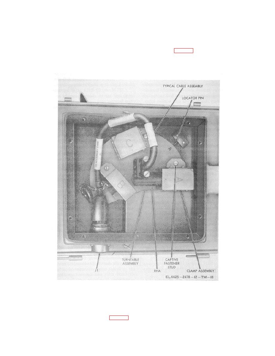 TM 11-6625-2478-12
(24) Close camp assembly A and secure with captive
(21) Loosen 10 captive fastener studs securing the
fastener stud.
welded plate assembly cover and remove cover.
(25) Rotate turntable assembly for maximum access
(22) Loosen captive fastener stud securing damp
connector J1 (fig. 3-11).
assembly A and remove IP-1080/AYA-10 from the
(26) Disconnect connector P1 of cable CX-2728 /U
clamp assembly.
from connector J1 on internal sic of the CY- 7117/AYM-
(23) Disconnect connector P1 of cable CX-12728- /U,
9.
removing
the
IP-1080/AYA-10.
Figure 3-11. Typical installation of RHAT for testing.
d. SLA RHA Test Procedures.
(3) Mount SLAR RHA on clamp assembly C up to
stop and secure clamp assembly by means of captive
(1) Connect connector P1 of Cable Assembly,
fastener stud.
Special Purpose, Electrical, CX-2727/U to the internal
(4) Mount welded plate assembly cover on top of the
sic of connector J1 on CY-7ll7/AYM-9.
Connect
connector P2 to connector on the SLAR RHA (fig. 3-11).
welded plate and secure with 10 captive fastener studs.
3-11
(2) Rotate turntable of the KE-59A until spring-
loaded locator pin locks into position C.
|
|
Privacy Statement - Press Release - Copyright Information. - Contact Us |
