 |
|||
|
|
|||
|
Page Title:
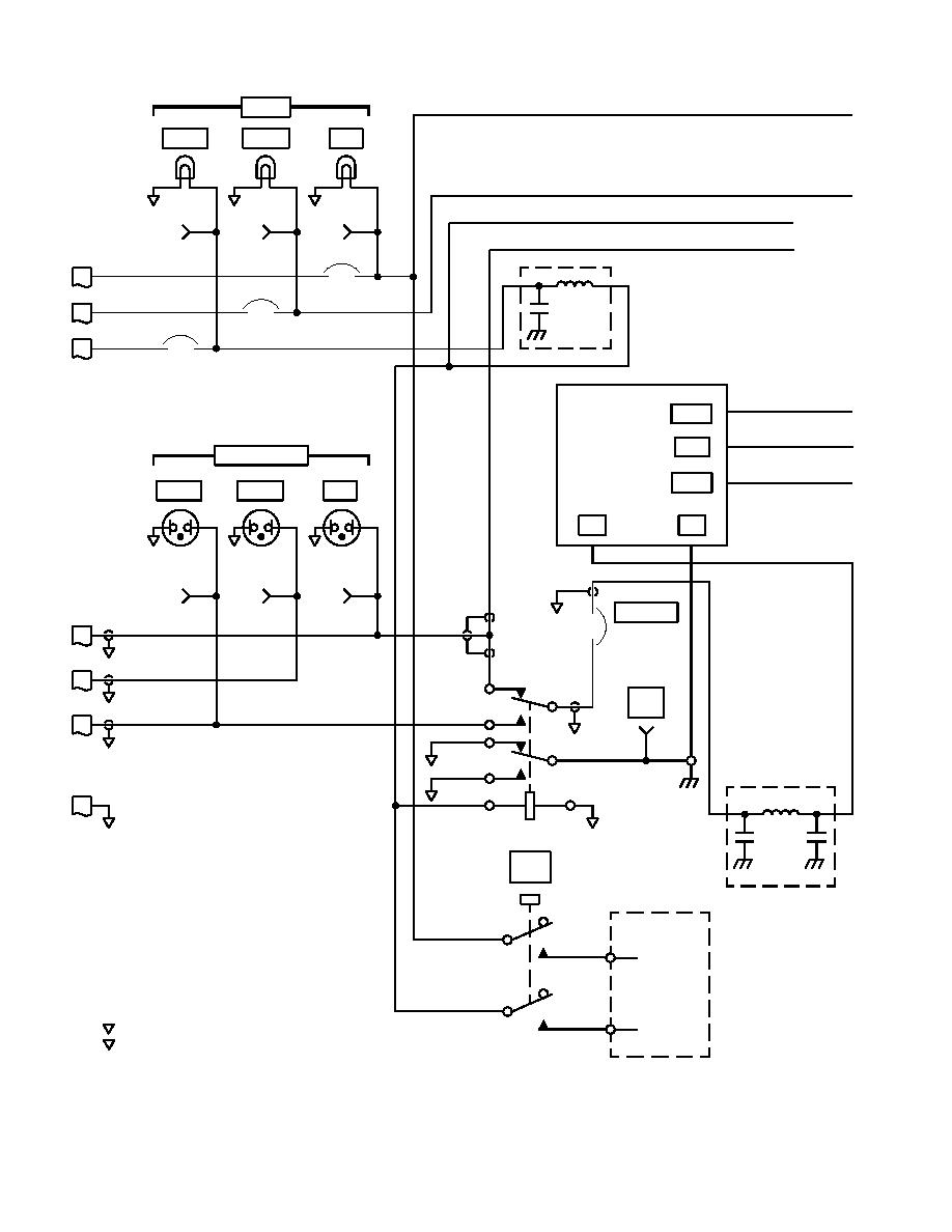
Figure 5-12. Test Set, Lower Panel Assembly Schematic Diagram (Sheet 1) |
|
||
| ||||||||||
|
|
 TM 1-6625-735-14
28 VDC
STAB1
STAB2
SAS
DS3
G
DS2
G
DS1
G
1
1
1
2
2
2
P1
P2
P3
J34
J33
J35
MANUAL
SLEW 1
115 VAC
CB1
SAS
J3
1
2
28 VDC
2
C
AMP
CB2
FL4
J2
1
2
28 VDC
U
2
AMP
CB3
J1
28 VDC 1
2
2
U
AMP
PSI
+OUT
T/C
115 VAC 400 HZ
-OUT
STAB1
STAB2
SAS
R
R
R
AC
AC
P1
P2
P3
DS6
DS5
DS4
J38
J37
J36
P1
TEST SET
J3
1
115 VAC
CB4
AMP
A
P3
J2
115 VAC
A3
M
A2
PWR
P2
J1
GND
115 VAC
A1
M
P1
J42
B3
P1
E1
B2
P3
B1
J3
X2
X1
P1
FL1
B
P3
P1
K1
LAMP
TEST
NC
NOTES
PART OF A3
C
(A)
G22
1. ALL RESISTANCE IS IN OHMS, 1/8
NO
WATT, 1% UNLESS OTHERWISE
PTT-2
INDICATED.
2. ALL CAPACITANCE IS IN UF.
NC
(B)
C
3. ALL DIODES ARE 1N645A UNLESS
OTHERWISE INDICATED.
G17
NO
4.
PTT-1
P INDICATES POWER GROUND.
AK3088_1
S INDICATES SIGNAL GROUND.
S24
SA
(5-45 Blank)/5-46
|
|
Privacy Statement - Press Release - Copyright Information. - Contact Us |
